30 posts tagged with "xeokit"
Xeokit tag description
View All TagsBuilding 3D Model Viewers with xeokit-webcomponents
Integrating 3D models into web applications can be a complex task, often requiring extensive knowledge of WebGL, 3D rendering pipelines, and model loading formats. However, with the advent of Web Components, this process has become significantly simpler. @xeokit/xeokit-webcomponents
leverages this power, providing a set of easy-to-use, framework-agnostic custom elements for displaying and interacting with 3D models, particularly useful for BIM and IFC data.
In this blog post, we'll explore how to get started with @xeokit/xeokit-webcomponents
and create a basic 3D model viewer.
Backfaces in xeokit
Introduction
On a triangle mesh geometry, backfaces are those faces which are oriented away from the viewpoint. Whenever possible, the xeokit viewer tries to avoid drawing backfaces, in order to reduce work done by the graphics hardware and speed up interactivity.
2D Overlay
One of a commonly used features of a BIM viewer is displaying a 2D overlay (e.g. a floor plan) within the 3D model. This article demonstrates how such an overlay can be implemented with xeokit, by using general purpose abstractions provided by the SDK.
- 1. Scene setup
- 2. Overlay image loading
- 3. Overlay mesh creation
- 4. Floor plan adjustment
- 5. Complete example
- 6. Interactive Overlay fitting (advanced)
1. Scene setup
The example starts with a minimalist scene that loads the Schependomlaan.ifc.xkt
model, and places a SectionPlane
that cuts through the first floor at the height of 1 unit:
<!doctype html>
<html>
<body style="overflow-y: hidden; overflow-x: hidden; margin: 0; width: 100%; height: 100%;">
<canvas id="myCanvas" style="position: absolute; width: 100%; height: 100%; background-image: linear-gradient(lightblue, white);"></canvas>
</body>
<script type="module">
import { SectionPlanesPlugin, Viewer, XKTLoaderPlugin } from "https://cdn.jsdelivr.net/npm/@xeokit/xeokit-sdk/dist/xeokit-sdk.es.min.js";
const viewer = new Viewer({ canvasId: "myCanvas" });
viewer.camera.eye = [7, 30, -8];
viewer.camera.look = [7, 0, -10];
viewer.camera.up = [0, 1, 0];
new XKTLoaderPlugin(viewer).load({ src: "../../assets/models/xkt/v8/ifc/Schependomlaan.ifc.xkt" });
new SectionPlanesPlugin(viewer, { overviewVisible: false }).createSectionPlane({ pos: [0, 1, 0], dir: [0, -1, 0] });
// ...
</script>
</html>
The model renders as follows:
2. Overlay image loading
The 2D overlay will display a floor plan from the schependomlaanPlanView.png
image.
The image is loaded before it's used as a texture:
// ...
import { buildPlaneGeometry, math, Mesh, PhongMaterial, ReadableGeometry, Texture } from "https://cdn.jsdelivr.net/npm/@xeokit/xeokit-sdk/dist/xeokit-sdk.es.min.js";
const image = new Image();
image.src = "../../assets/images/schependomlaanPlanView.png";
image.onload = function() {
// Create the floor plan Texture
const scene = viewer.scene;
const planTexture = new Texture(scene, { image: image });
// ...
};
3. Overlay mesh creation
The overlay is created by combining a Mesh
, a plane geometry, and a PhongMaterial
:
// ...
image.onload = function() {
// Create the floor plan Texture
// ...
// Create the floor plan Mesh
const planMesh = new Mesh(scene, {
pickable: false,
geometry: new ReadableGeometry(scene, buildPlaneGeometry()),
material: new PhongMaterial(scene, {
alpha: 0.75,
diffuse: [0, 0, 0],
diffuseMap: planTexture,
emissiveMap: planTexture,
backfaces: true
})
});
// ...
};
Unless the floor plan mesh is to be interacted with, it's advised to use the pickable: false
flag, to avoid the mesh interfering with the Scene::Pick
method calls.
The specific Material
settings are highly application-specific, and it's encouraged for the SDK users to experiment with them.
One of the parameters that's advised to be used though is backfaces: true
, which will make the floor plan visible from both the front and back side.
4. Floor plan adjustment
Finally, the floor plan mesh is positioned and scaled to match the model's layout. The overlay is placed at the height of 0.1 unit, which is slightly above the first floor level. The value of the scale, as well as the X and Z coordinates, has been determined empirically to fit the model in the example.
// ...
image.onload = function() {
// Create the floor plan Texture
// ...
// Create the floor plan Mesh
// ...
// Scale and position the Mesh
const planHeight = 0.1
const planPosition = [ 10.946, planHeight, -10.343 ];
const planScale = 22.66;
const t = math.translationMat4v(planPosition);
// Preserve image's aspect ratio when scaling
const s = math.scalingMat4v([planScale * image.width / image.height, 1, planScale]);
planMesh.matrix = math.mulMat4(t, s, math.mat4());
};
The floor plan adjusted to the model looks as below:
5. Complete example
The complete example is presented below:
<!doctype html>
<html>
<body style="overflow-y: hidden; overflow-x: hidden; margin: 0; width: 100%; height: 100%;">
<canvas id="myCanvas" style="position: absolute; width: 100%; height: 100%; background-image: linear-gradient(lightblue, white);"></canvas>
</body>
<script type="module">
import { SectionPlanesPlugin, Viewer, XKTLoaderPlugin } from "https://cdn.jsdelivr.net/npm/@xeokit/xeokit-sdk/dist/xeokit-sdk.es.min.js";
const viewer = new Viewer({ canvasId: "myCanvas" });
viewer.camera.eye = [7, 30, -8];
viewer.camera.look = [7, 0, -10];
viewer.camera.up = [0, 1, 0];
new XKTLoaderPlugin(viewer).load({ src: "../../assets/models/xkt/v8/ifc/Schependomlaan.ifc.xkt" });
new SectionPlanesPlugin(viewer, { overviewVisible: false }).createSectionPlane({ pos: [0, 1, 0], dir: [0, -1, 0] });
import { buildPlaneGeometry, math, Mesh, PhongMaterial, ReadableGeometry, Texture } from "https://cdn.jsdelivr.net/npm/@xeokit/xeokit-sdk/dist/xeokit-sdk.es.min.js";
const image = new Image();
image.src = "../../assets/images/schependomlaanPlanView.png";
image.onload = function() {
// Create the floor plan Texture
const scene = viewer.scene;
const planTexture = new Texture(scene, { image: image });
// Create the floor plan Mesh
const planMesh = new Mesh(scene, {
pickable: false,
geometry: new ReadableGeometry(scene, buildPlaneGeometry()),
material: new PhongMaterial(scene, {
alpha: 0.75,
diffuse: [0, 0, 0],
diffuseMap: planTexture,
emissiveMap: planTexture,
backfaces: true
})
});
// Scale and position the Mesh
const planHeight = 0.1
const planPosition = [ 10.946, planHeight, -10.343 ];
const planScale = 22.66;
const t = math.translationMat4v(planPosition);
// Preserve image's aspect ratio when scaling
const s = math.scalingMat4v([planScale * image.width / image.height, 1, planScale]);
planMesh.matrix = math.mulMat4(t, s, math.mat4());
};
</script>
</html>
6. Interactive Overlay fitting (advanced)
The workflow presented above places a 2D overlay inside a 3D scene with a known transformation (a translation and a scale in this case).
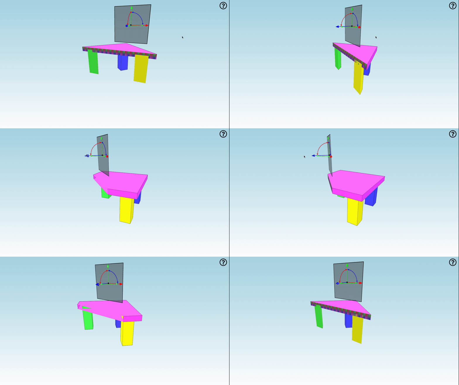
Another common scenario might be a feature that lets end user to instantiate an overlay in a scene, and then to fit it interactively to a model. There are many possible ways such an interaction could be achieved, relying on end user's input devices. Ultimately the specifics of the interaction that match application's UX need to be determined by the viewer code outside of the SDK. xeokit SDK’s repository provides an example of a "fitting" interaction, that's presented at https://xeokit.github.io/xeokit-sdk/examples/scenegraph/#floorPlan_mouseEdit.
The interaction uses mouse input in a sequence of steps:
- A cyan colored dot needs to be placed over the 2D overlay.
- After the left mouse button is clicked, the overlay will start following the mouse cursor, anchored at the location the overlay was clicked at.
- Next mouse click will fix the overlay to a translated position.
- Another yellow dot needs to be placed over another part of the overlay.
- After the mouse button is clicked, the overlay will start rotating and scaling up or down along with the the mouse cursor.
5a. If the
Ctrl
key is pressed while rotating and scaling the overlay with a mouse, the rotation gets locked to 9° steps, which might be helpful in preserving overlay’s current rotation. - Final mouse click will "settle" the overlay with its current translation and scale.
This demonstrative interaction is implemented as the setupOverlayAlignmentControl
function at https://github.com/xeokit/xeokit-sdk/blob/master/examples/scenegraph/overlay.js.
The code that employs the function is as follows:
// ...
import { setupOverlayAlignmentControl } from "./overlay.js";
image.onload = function() {
// Create the floor plan Texture
// ...
// Create the floor plan Mesh
// ...
// Scale and position the Mesh
// ...
// Use the illustrative alignment control to put the overlay in the desired place
const overlayCtrl = setupOverlayAlignmentControl(viewer, planMesh);
window.document.addEventListener("keydown", e => overlayCtrl.setStepRotation(e.shiftKey));
window.document.addEventListener("keyup", e => overlayCtrl.setStepRotation(e.shiftKey));
};
IMPORTANT: It’s important to understand that this particular “fitting” interaction has been provided as an example or a guideline for viewer programmers on how to implement such a feature on top of the xeokit SDK. Rather than relying on the function's particular location and implementation, users are encouraged to copy its code to their own viewers, and adjust according to their specific UX requirements.
Textures in Scene Representations
See also: Textures in XKT Model Format
- Introduction
- Building VBOSceneModels Containing Textures
- Loading KTX2 files into a VBOSceneModel
- Loading KTX2 ArrayBuffers into a VBOSceneModel
Introduction
In this tutorial, we'll use xeokit's convert2xkt
CLI tool to convert a binary glTF model with textures into xeokit's native XKT geometry format, which we'll then view in the browser using a xeokit Viewer.
The XKT format compresses models into a compact payload from which xeokit can load large numbers of objects over the Web in seconds, at full geometric precision.
XKT stores textures in such a way that, as they are loaded, they are transcoded within the browser straight to the optimal compressed format that’s supported by the user’s GPU. Transcoding consumes minimal browser resources, and the GPU footprint of the compressed textures is also minimal. This gives us a minimal memory spike while loading textures, and the ability to pack more more them onto our GPU.
To achieve this, XKT stores each texture in the KTX 2.0 Container Format (.ktx2
) . Within each KTX2 container, the texture’s pixel data is is encoded in the UASTC Transmission Format. The UASTC format is designed to be efficiently transcoded into the optimal compressed format for the target GPU.
Internally, convert2xkt uses the Basis Universal Transcoder to convert the glTF textures into XKT textures. Likewise, XKTLoaderPlugin uses the Basis Transcoder to transcode the XKT textures to the GPU’s optimal format.
For our glTF model, we'll use an architectural model from Sketchfab. When that's converted and loaded into our viewer, it will look like the example below.
This model contains 571 visible objects, with 139642 triangles and 14 textures, and a xeokit Viewer can usually load it over a good Internet connection in ~2 seconds.
Building VBOSceneModels Containing Textures
A VBOSceneModel that is configured with a KTX2TextureTranscoder will allow us to create textures within it from KTX2 data. In the next two examples, we’ll show how to use this component to programmatically build 3D scene content containing KTX2 textures.
Loading KTX2 files into a VBOSceneModel
In the example below, we'll create a Viewer, containing a VBOSceneModel configured with a KTX2TextureTranscoder.
We'll then programmatically create a simple object within the VBOSceneModel, consisting of a single box mesh with a texture loaded from a KTX2 file, which our VBOSceneModel internally transcodes, using its KTX2TextureTranscoder.
As in the previous example, we'll configure our KTX2TextureTranscoder to load the Basis Codec from a local directory. If we were happy with loading the Codec from our CDN (ie. our app will always have an Internet connection) then we could just leave out the KTX2TextureTranscoder altogether, and let the VBOSceneModel use its internal default KTX2TextureTranscoder.
const viewer = new Viewer({
canvasId: "myCanvas",
transparent: true
});
viewer.scene.camera.eye = [-21.80, 4.01, 6.56];
viewer.scene.camera.look = [0, -5.75, 0];
viewer.scene.camera.up = [0.37, 0.91, -0.11];
const textureTranscoder = new KTX2TextureTranscoder({
viewer,
transcoderPath: "./../dist/basis/" // <------ Path to BasisU transcoder module
});
const vboSceneModel = new VBOSceneModel(viewer.scene, {
id: "myModel",
textureTranscoder // <<---------- Configure model with our transcoder
});
vboSceneModel.createTexture({
id: "myColorTexture",
src: "sample_uastc_zstd.ktx2" // <<----- KTX2 texture asset
});
vboSceneModel.createTexture({
id: "myMetallicRoughnessTexture",
src: "crosshatchAlphaMap.jpg" // <<----- JPEG texture asset
});
vboSceneModel.createTextureSet({
id: "myTextureSet",
colorTextureId: "myColorTexture",
metallicRoughnessTextureId: "myMetallicRoughnessTexture"
});
vboSceneModel.createMesh({
id: "myMesh",
textureSetId: "myTextureSet",
primitive: "triangles",
positions: [1, 1, 1, ...],
normals: [0, 0, 1, 0, ...],
uv: [1, 0, 0, ...],
indices: [0, 1, 2, ...],
});
vboSceneModel.createEntity({
id: "myEntity",
meshIds: ["myMesh"]
});
vboSceneModel.finalize();
Loading KTX2 ArrayBuffers into a VBOSceneModel
A VBOSceneModel that is configured with a KTX2TextureTranscoder will also allow us to load textures into it from KTX2 ArrayBuffers.
In the example below, we'll create a Viewer, containing a VBOSceneModel configured with a KTX2TextureTranscoder.
We'll then programmatically create a simple object within the VBOSceneModel, consisting of a single mesh with a texture loaded from a KTX2 ArrayBuffer, which our VBOSceneModel internally transcodes, using its KTX2TextureTranscoder.
const viewer = new Viewer({
canvasId: "myCanvas",
transparent: true
});
viewer.scene.camera.eye = [-21.80, 4.01, 6.56];
viewer.scene.camera.look = [0, -5.75, 0];
viewer.scene.camera.up = [0.37, 0.91, -0.11];
const textureTranscoder = new KTX2TextureTranscoder({
viewer,
transcoderPath: "./../dist/basis/" // <--- Path to BasisU transcoder module
});
const vboSceneModel = new VBOSceneModel(viewer.scene, {
id: "myModel",
textureTranscoder // <<----------- Configure model with our transcoder
});
utils.loadArraybuffer("sample_uastc_zstd.ktx2",(arrayBuffer) => {
vboSceneModel.createTexture({
id: "myColorTexture",
buffers: [arrayBuffer] // <<----- KTX2 texture asset
});
vboSceneModel.createTexture({
id: "myMetallicRoughnessTexture",
src: "crosshatchAlphaMap.jpg" // <<----- JPEG texture asset
});
vboSceneModel.createTextureSet({
id: "myTextureSet",
colorTextureId: "myColorTexture",
metallicRoughnessTextureId: "myMetallicRoughnessTexture"
});
vboSceneModel.createMesh({
id: "myMesh",
textureSetId: "myTextureSet",
primitive: "triangles",
positions: [1, 1, 1, ...],
normals: [0, 0, 1, 0, ...],
uv: [1, 0, 0, ...],
indices: [0, 1, 2, ...],
});
vboSceneModel.createEntity({
id: "myEntity",
meshIds: ["myMesh"]
});
vboSceneModel.finalize();
});
Dynamically Repositioning Models
In xeokit v2.4, we have added the ability to dynamically reposition a model within xeokit's double-precision coordinate system. This means that once a model is loaded, it can be moved to any location within the full extents of xeokit’s double-precision coordinate system. This feature allows us to load a BIM model from an XKT file and a point cloud from an LAZ file, and then reposition either model to align them with each other.
A model can be dynamically translated and rotated, but cannot be scaled. Disallowing scaling of models is necessary for this mechanism to work efficiently within xeokit’s double-precision coordinate system.
Localization in xeokit
In this guide, we'll introduce how to localize xeokit, so that we can dynamically it between different languages. Specifically, we'll show how to localize xeokit's core Viewer component and plugins, and how to localize xeokit's bundled BIM viewer application.
Positioning an IFC Model at Mercator-Projected Geodesic Coordinates
In this tutorial, you'll learn how to load an IFC model into a xeokit Viewer, and position it within the Viewer's double-precision 3D Cartesian World coordinate system using mercator-projected geodesic coordinates (longitude, latitude and height).
Saving and Loading BCF Viewpoints
A xeokit viewer can exchange BCF viewpoints with other BIM software, allowing us to use the viewer to report and view issues in BIM models. In this tutorial, we'll demonstrate this capability by creating a BCF viewpoint with a xeokit viewer, which we'll then import it into a second xeokit viewer.
Scene Representation and Metadata
In this guide, we'll use convert2xkt to convert an IFC file to xeokit's native, fast-loading XKT format. Then, using JavaScript, we'll view the XKT model in the browser using xeokit Viewer component. As the Viewer loads our model, it will create 3D scene objects, along with a parallel metadata structure. We'll show how to use that metadata to navigate the scene objects and get information about them.